How many times have you seen a classic movie in which the hero has to defuse a ? The hero watches the display as time passes, each second more valuable than the last. Well, if you look closely, you’ll notice that all of the in movies have seven-segment displays. It must be! How else could a hero know how much time he has left?
Perhaps you do not find seven-segment displays to be visually appealing, but they are the most efficient way to display numbers. They are simple to use, inexpensive, and highly visible in both low- and high-light conditions.
A real-world example of a seven-segment display is NASA’s famous countdown clock at Cape Canaveral, Florida, which was used for the Apollo landing.

The 7-Segment Display
The 7-segment display, also written as “seven segment display”, consists of seven LEDs arranged in a ‘8’-shaped pattern. Each LED is referred to as a segment, because when illuminated, it forms part of a digit. An eighth LED is sometimes used to indicate a decimal point.
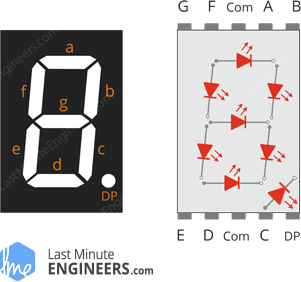
Each segment LED has one of its connection pins brought directly out of the rectangular plastic package. These pins are labeled with the letters ‘a’ through ‘g’. The remaining LED pins are wired together to form a single common pin.
Each segment can be individually turned on or off by setting the corresponding pin to HIGH or LOW, just like a regular LED. By lighting up individual segments, you can create any numerical character and even some basic representations of letters.
7-Segment Display Pinout
Now, let’s review the segment configuration so you know which pin corresponds to which segment. The 7-segment display pinout is as follows.

a, b, c, d, e, f, g, and DP are connected to the digital pins on an Arduino to operate the display’s individual segments. By lighting up individual segments, you can create any numeric character.
COM The pins 3 and 8 are connected internally to form a common pin. Depending on the type of display, this pin must be connected to either GND (common cathode) or 5V (common anode).
Common Cathode(CC) vs Common Anode(CA)
There are two types of seven segment displays: common cathode (CC) and common anode (CA).
The internal structure of both types is nearly identical. The difference is the polarity of the LEDs and the common terminal. As the name implies, in common cathode displays, all of the cathodes (or negative terminals) of the segment LEDs are tied together, whereas in common anode displays, all of the anodes (or positive terminals) of the segment LEDs are tied together.
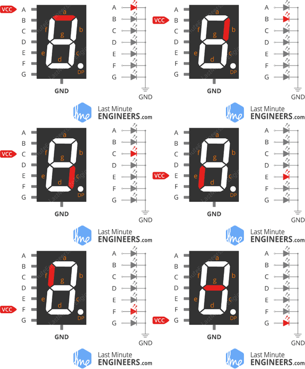
In a common cathode display, the com pin is connected to GND, and a positive voltage is applied to each segment (a-g) to illuminate it.
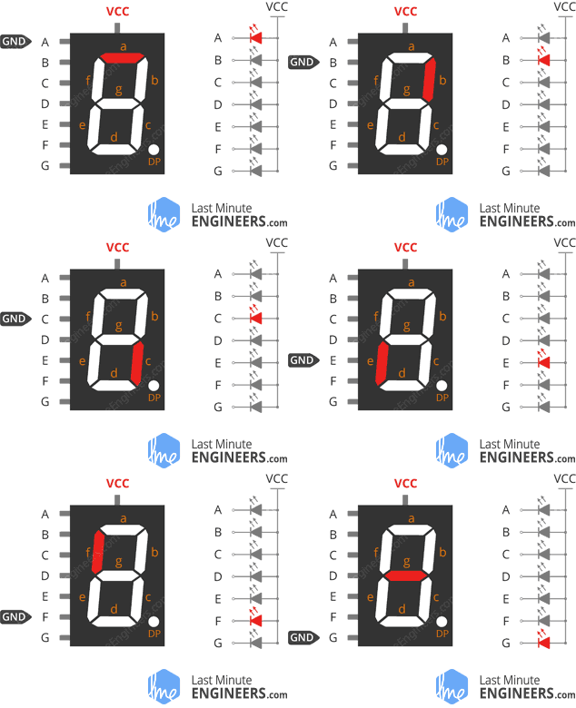
In a common anode display, the com pin is connected to VCC, and each segment (a-g) is individually grounded to illuminate it.
Common anode 7-segment displays are more widely used in general because current sinking circuits have many advantages over current sourcing circuits.
7-Segment Display Working
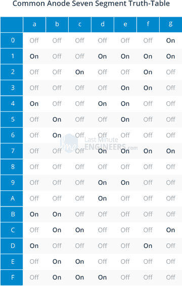
Depending on the character you wish to display, you must illuminate the appropriate segment LEDs. To display the number 4, for example, four LED segments b, c, f, and g must be illuminated. Similarly, various digits from 0 to 9 and characters from A to F can be displayed on a 7-segment display, as shown below.

The truth table below shows which segments must be lit to produce digits and characters. Notice that the truth table for the common anode 7-segment display is the exact opposite of that for the common cathode 7-segment display.

Selecting a Current-Limiting Resistor
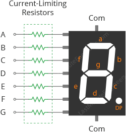
A 7-segment display may appear to be a single display, but it is actually made up of seven independent LEDs housed in a single package, each of which requires its own current-limiting resistor to prevent damage to the LED segments.
Typically, for a standard red 7-segment display, each LED segment requires approximately 15 mA to illuminate correctly; therefore, on a 5 volt digital logic circuit, the value of the current-limiting resistor would be approximately 200Ω (5v – 2v)/15mA, or 220Ω to the nearest higher preferred value.
With a 220Ω, the display’s brightness will be slightly reduced. That’s fine, because these displays are pretty bright, so under-driving them a little bit usually makes them look better. If you plan to use them outside, though, you’ll want to use a 150Ω resistor for maximum brightness.
If you’re using a different color 7-segment display and aren’t sure how much current each LED segment requires, 330Ω is a safe value.
The following figure shows how current-limiting resistors are connected to the display’s LED segments.
Wiring a 7-Segment Display to an Arduino
Now that we understand how the 7-segment display works, we can connect it to the Arduino!
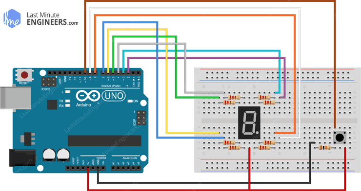
Begin by mounting the 7-segment display on your breadboard, making sure that each side of the display is on a different side of the breadboard. With the decimal point facing downwards, the pins are 1-5 on the bottom side from left to right and 10-6 on the upper side from left to right.
Connect one of the COM pins to the Arduino’s 5V pin (if using a common anode 7-segment display) or to the Arduino’s GND pin (if you are using a common cathode 7-segment display).
The four pins on the upper side (b, a, f, and g) are connected to Arduino’s digital pins 2 through 5, while the remaining four pins on the lower side (e, d, c, and DP) are connected to Arduino’s digital pins 6 through 9.
While the display may function without current-limiting resistors, having them in your circuit is always a good idea to protect the display from being damaged by overcurrent. So you’ll also need eight 220Ω current-limiting resistors for each segment.
The following table lists the pin connections:
| 7-Segment Display | Arduino | Notes | |
| a | 3 | via 220Ω | |
| b | 2 | via 220Ω | |
| c | 8 | via 220Ω | |
| d | 7 | via 220Ω | |
| e | 6 | via 220Ω | |
| f | 4 | via 220Ω | |
| g | 5 | via 220Ω | |
| DP | 9 | via 220Ω | |
| COM | 5V | only for common anode display | |
| COM | GND | only for common cathode display |
The figure below shows how to connect everything.


The SevSeg Library
There are many libraries available for the 7-segment display, but one of the most popular is SevSeg. This library has been around for a long time. It’s simple to use for beginners while still providing a lot for advanced users. We will use this library in our examples.
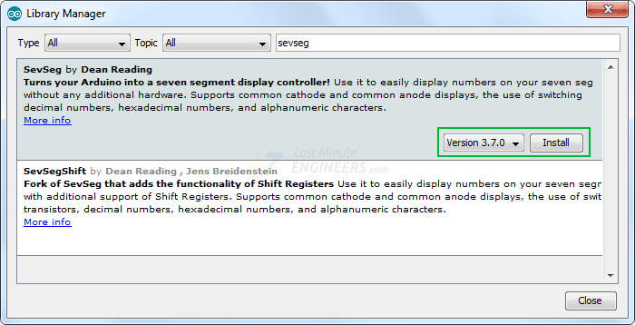
To install the library, navigate to Sketch > Include Library > Manage Libraries… Wait for the Library Manager to download the libraries index and update the list of installed libraries.

Filter your search by entering ‘sevseg‘. Look for the SevSeg library by Dean Reading. Click on that entry and then choose Install.
Arduino Example Code
Now, it’s time to light up the display with some code.
The following test sketch will count from 0 to 9. Try out the sketch, and then we’ll go over it in more detail.
#include "SevSeg.h"SevSeg sevseg;void setup(){//Set to 1 for single digit displaybyte numDigits = 1;//defines common pins while using multi-digit display. Left empty as we have a single digit displaybyte digitPins[] = {};//Defines arduino pin connections in order: A, B, C, D, E, F, G, DPbyte segmentPins[] = {3, 2, 8, 7, 6, 4, 5, 9};bool resistorsOnSegments = true;//Initialize sevseg object. Uncomment second line if you use common cathode 7 segmentsevseg.begin(COMMON_ANODE, numDigits, digitPins, segmentPins, resistorsOnSegments);//sevseg.begin(COMMON_CATHODE, numDigits, digitPins, segmentPins, resistorsOnSegments);sevseg.setBrightness(90);}void loop(){ //Display numbers one by one with 2 seconds delay for(int i = 0; i < 10; i++) { sevseg.setNumber(i); sevseg.refreshDisplay(); delay(2000); }}Code Explanation:
At the beginning of the sketch, we include the SevSeg library and create a SevSeg object, which we will use throughout the sketch.
// Include library#include "SevSeg.h"// Create objectSevSeg sevseg;The next step is to specify the number of digits on the display. Because we are using a one-digit display, we set numDigits to 1. If you are using a four-digit display, set this value to 4.
// Number of digits in displaybyte numDigits = 1;The digitPins array simply specifies the ‘common pins’. If you have a single digit display, leave it blank. Otherwise, list the arduino pin numbers to which the ‘common pins’ of individual digits are connected, from left to right.
// Specifies the 'common pins' while using multi-digit display.// If you have a single digit display, leave it blank.byte digitPins[] = {};The array segmentPins is then defined. This is an array of the I/O pins that are wired to the LED segments, in the order A, B, C, D, E, F, G, DP.
// Display segment pins A,B,C,D,E,F,G,DPbyte segmentPins[] = {3, 2, 8, 7, 6, 4, 5, 9};A boolean variable, resistorsOnSegments, is also defined to inform the library whether we are using current-limiting resistors.
// Dropping resistors usedbool resistorsOnSegments = true;The hardwareConfig variable specifies the type of 7-segment display we’re using. Valid values are COMMON ANODE and COMMON CATHODE. Ours is a common anode display.
// Display typebyte hardwareConfig = COMMON_ANODE;In Setup, we initialize the display object with the arguments we just defined. We also configure the display’s brightness; any value between 0 and 150 will work.
void setup() { // Start display object sevseg.begin(hardwareConfig, numDigits, digitPins, segmentPins, resistorsOnSegments); // Set brightness sevseg.setBrightness(90);}In the Loop, the for loop is used to count from 0 to 9. Every iteration, the function setNumber() and refreshDisplay() are used to print a digit to the display.
Then, there is a delay of one second before i is incremented and the next number is displayed.
for(int i = 0; i < 10; i++){ sevseg.setNumber(i); sevseg.refreshDisplay(); delay(1000);}Arduino Project – Electronic Dice Roller
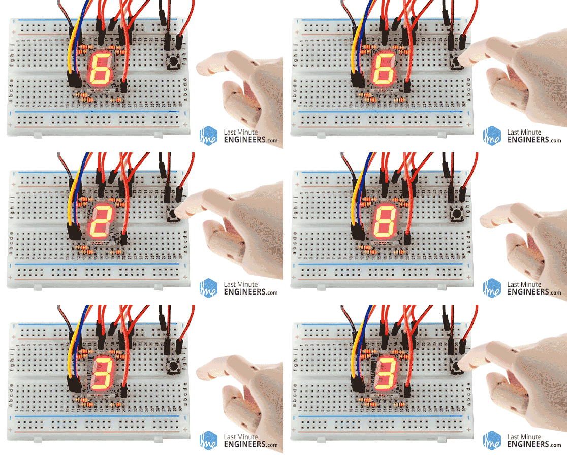
Let’s create a project that automatically rolls the dice for fun dice games like Yahtzee and Ludo. This is what the output looks like.
Excited? Let’s get started!
Wiring
We’ll use the same Arduino setup as in the previous example, but this time we’ll add a tactile switch for rolling.
Arduino Code
#include "SevSeg.h"SevSeg sevseg; const int buttonPin = 10; // the number of the pushbutton pin// variables will change:int buttonState = 0; // variable for reading the pushbutton statusvoid setup(){ byte numDigits = 1; byte digitPins[] = {}; byte segmentPins[] = {3, 2, 8, 7, 6, 4, 5, 9}; bool resistorsOnSegments = true; sevseg.begin(COMMON_ANODE, numDigits, digitPins, segmentPins, resistorsOnSegments); sevseg.setBrightness(90);// initialize the pushbutton pin as an input:pinMode(buttonPin, INPUT);}void loop(){// read the state of the pushbutton value:buttonState = digitalRead(buttonPin); if (buttonState == HIGH) {sevseg.setNumber(random(1,7));sevseg.refreshDisplay(); }}Code Explanation:
This sketch is similar to the last one, except for a few differences.
At the start, we declare the Arduino pin to which the pushbutton is connected. In addition, a new variable buttonState is defined to keep track of the status of the pushbutton.
// the number of the pushbutton pinconst int buttonPin = 10; // variable for reading the pushbutton statusint buttonState = 0;In the Setup, we configure the buttonPin as an input.
// initialize the pushbutton pin as an input:pinMode(buttonPin, INPUT);In the Loop, whenever a button press is detected we generate a random number using the built-in function random(min, max), which takes two parameters: the first specifies the lower bound of the random value (including this number), while the second specifies the upper bound (excluding this number). Meaning a random number will be generated between min and max-1.
void loop() { // read the state of the pushbutton value: buttonState = digitalRead(buttonPin); if (buttonState == HIGH) { sevseg.setNumber(random(1,7)); sevseg.refreshDisplay(); }}