Have you ever watched a classic movie where the hero faces a ticking time bomb? You know the scene – the hero stares intently at the countdown, every passing second crucial. Well, if you pay attention, you’ll notice that all the countdown timers in movies feature seven-segment displays. It’s a must-have! How else could the hero keep track of the dwindling time?
You might not find seven-segment displays particularly attractive, but they’re the most efficient way to showcase numbers. They’re straightforward, cost-effective, and easily visible in various lighting conditions, whether dim or bright.
A prime real-world example of a seven-segment display is NASA’s renowned countdown clock at Cape Canaveral, Florida, famously employed during the Apollo moon landing missions.

Table of Contents
Parts Required
| Component Name | Buy Now |
| Arduino Uno REV3 | Amazon |
| Common Cathode 10 Pin 1 Bit 7 Segment Display | Amazon |
| Common Anode 10-Pin 1 Bit 7 Segment Display | Amazon |
Please Note:These are affiliate links. I may make a commission if you buy the components through these links. I would appreciate your support in this way!
The 7-Segment Display
The 7-segment display, alternatively spelled as “seven segment display,” comprises seven LEDs arranged in a figure-eight pattern. Each LED, termed a segment, contributes to forming a digit when illuminated. Occasionally, an eighth LED is employed to denote a decimal point.

One of the connection pins for each segment LED extends directly from the rectangular plastic casing. These pins are marked with the letters ‘a’ through ‘g’. The remaining LED pins are interconnected to establish a single common pin.
Each segment can be activated or deactivated independently by setting the corresponding pin to either HIGH or LOW, akin to a standard LED. By illuminating specific segments, it’s possible to generate any numerical character and even rudimentary representations of letters.
7-Segment Display Pinout
Let’s delve into the segment configuration to understand which pin corresponds to each segment on the 7-segment display. Here’s the pinout layout:
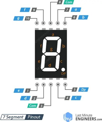
The pins labeled a, b, c, d, e, f, g, and DP are linked to the digital pins on an Arduino to control the individual segments of the display. By activating specific segments, you can form any numeric character.
COM: Pins 3 and 8 are internally linked to create a common pin. Depending on the display type, this pin should be connected to either GND (for common cathode) or 5V (for common anode) configurations.
Common Cathode(CC) vs Common Anode(CA)
Two types of seven-segment displays exist: common cathode (CC) and common anode (CA).
Internally, both types share nearly identical structures. However, they differ in LED polarity and the common terminal. In common cathode displays, all cathodes (or negative terminals) of the segment LEDs are interconnected. Conversely, in common anode displays, all anodes (or positive terminals) of the segment LEDs are connected.
In a common cathode display, the COM pin links to GND, while a positive voltage is applied to each segment (a-g) to illuminate it.

For a common anode display, the COM pin links to VCC, and each segment (a-g) is grounded individually to illuminate.

Common anode 7-segment displays are generally more prevalent because current sinking circuits offer numerous advantages over current sourcing circuits.
Working Principle of 7-Segment Displays
To showcase a specific character, the corresponding segment LEDs must be activated. For instance, to display the number 4, segments b, c, f, and g should be illuminated. Likewise, various digits ranging from 0 to 9 and characters from A to F can be exhibited on a 7-segment display, as depicted below.

The provided truth table illustrates the segments required to be lit for displaying digits and characters. Notably, the truth table for a common anode 7-segment display is the inverse of that for a common cathode 7-segment display.


Choosing a Current-Limiting Resistor
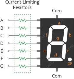
While a 7-segment display may seem like a single unit, it comprises seven distinct LEDs housed within a single package. Each LED necessitates its own current-limiting resistor to safeguard the LED segments from damage.
Typically, for a standard red 7-segment display, each LED segment demands around 15 mA to achieve proper illumination. Consequently, on a 5-volt digital logic circuit, the current-limiting resistor’s value would be approximately 200Ω, calculated as (5v – 2v)/15mA, or 220Ω rounded to the nearest higher preferred value.
Utilizing a 220Ω resistor may slightly dim the display’s brightness, which is acceptable since these displays are inherently bright, and slight under-driving often enhances their appearance. However, if intended for outdoor use, opting for a 150Ω resistor ensures maximum brightness.
For different colored 7-segment displays or when unsure about the current requirements of each LED segment, a 330Ω resistor provides a safe choice.
The accompanying diagram illustrates the connection of current-limiting resistors to the LED segments of the display.
Wiring a 7-Segment Display to an Arduino
Now that we have a grasp of how the 7-segment display operates, let’s link it up with the Arduino!
To begin, position the 7-segment display onto your breadboard, ensuring that each side of the display resides on opposite sides of the breadboard. Orient the display with the decimal point facing downward; the pins are numbered 1-5 on the bottom side from left to right, and 10-6 on the upper side from left to right.
Link one of the COM pins to the Arduino’s 5V pin (for a common anode 7-segment display) or to the Arduino’s GND pin (if employing a common cathode 7-segment display).
The four pins on the upper side (b, a, f, and g) should be connected to Arduino’s digital pins 2 through 5, while the remaining four pins on the lower side (e, d, c, and DP) are linked to Arduino’s digital pins 6 through 9.
Although the display might operate without current-limiting resistors, including them in your circuit is advisable to shield the display from potential damage due to overcurrent. Hence, you’ll require eight 220Ω current-limiting resistors for each segment.
Refer to the table below for the pin connections:
| 7-Segment Display | Arduino | Notes |
| a | 3 | via 220Ω |
| b | 2 | via 220Ω |
| c | 8 | via 220Ω |
| d | 7 | via 220Ω |
| e | 6 | via 220Ω |
| f | 4 | via 220Ω |
| g | 5 | via 220Ω |
| DP | 9 | via 220Ω |
| COM | 5V | only for common anode display |
| COM | GND | only for common cathode display |
The figure below shows how to connect everything.


The SevSeg Library
Among the various libraries tailored for the 7-segment display, one of the most widely embraced is the SevSeg library. This library has enjoyed a longstanding presence, offering simplicity for novices while encompassing substantial features for advanced users. In our demonstrations, we’ll be utilizing this library.
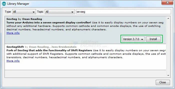
To incorporate the library into your Arduino environment, proceed to Sketch > Include Library > Manage Libraries… Allow the Library Manager time to fetch the libraries index and update the list of installed libraries.

Refine your search by typing ‘sevseg’. Locate the SevSeg library authored by Dean Reading. Click on the corresponding entry and opt for installation.
Arduino Example Code
Now, let’s illuminate the display with some code.
The subsequent test sketch will increment from 0 to 9. Experiment with the sketch, and afterward, we’ll delve into its intricacies.
#include "SevSeg.h"SevSeg sevseg;void setup(){//Set to 1 for single digit displaybyte numDigits = 1;//defines common pins while using multi-digit display. Left empty as we have a single digit displaybyte digitPins[] = {};//Defines arduino pin connections in order: A, B, C, D, E, F, G, DPbyte segmentPins[] = {3, 2, 8, 7, 6, 4, 5, 9};bool resistorsOnSegments = true;//Initialize sevseg object. Uncomment second line if you use common cathode 7 segmentsevseg.begin(COMMON_ANODE, numDigits, digitPins, segmentPins, resistorsOnSegments);//sevseg.begin(COMMON_CATHODE, numDigits, digitPins, segmentPins, resistorsOnSegments);sevseg.setBrightness(90);}void loop(){ //Display numbers one by one with 2 seconds delay for(int i = 0; i < 10; i++) { sevseg.setNumber(i); sevseg.refreshDisplay(); delay(2000); }}Code Explanation:
The initial segment of the sketch entails including the SevSeg library and creating a SevSeg object, which remains operative throughout the sketch.
// Include library#include "SevSeg.h"// Create objectSevSeg sevseg;
Next, we define the number of digits on the display. For a one-digit display, we set numDigits to 1. Adjust this value to 4 for a four-digit display.
// Number of digits in displaybyte numDigits = 1;
The digitPins array specifies the ‘common pins’. For a single digit display, this remains empty. Otherwise, enumerate the Arduino pin numbers connected to the ‘common pins’ of individual digits, left to right.
// Specifies the 'common pins' while using multi-digit display.// If you have a single digit display, leave it blank.byte digitPins[] = {};Subsequently, the segmentPins array is defined. This array contains the I/O pins linked to the LED segments, following the order A, B, C, D, E, F, G, DP.
// Display segment pins A,B,C,D,E,F,G,DPbyte segmentPins[] = {3, 2, 8, 7, 6, 4, 5, 9};A boolean variable, resistorsOnSegments, is established to convey to the library the usage of current-limiting resistors.
// Dropping resistors usedbool resistorsOnSegments = true;
The hardwareConfig variable denotes the type of 7-segment display being utilized. Options are COMMON ANODE and COMMON CATHODE. Here, we’re employing a common anode display.
// Display typebyte hardwareConfig = COMMON_ANODE;
Within the setup, we initialize the display object with the predefined arguments. Additionally, we set the display’s brightness, where any value from 0 to 150 is functional.
void setup() { // Start display object sevseg.begin(hardwareConfig, numDigits, digitPins, segmentPins, resistorsOnSegments); // Set brightness sevseg.setBrightness(90);}In the Loop section, a for loop is employed to count from 0 to 9. During each iteration, the setNumber() function and refreshDisplay() function are utilized to display a digit on the display.
Following each iteration, there’s a one-second delay before incrementing i and displaying the subsequent number.
for(int i = 0; i < 10; i++){ sevseg.setNumber(i); sevseg.refreshDisplay(); delay(1000);}Arduino Project – Electronic Dice Roller
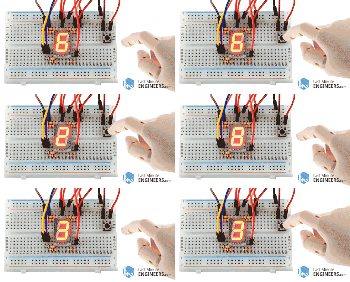
Let’s embark on a project to automate dice rolls for engaging dice games such as Yahtzee and Ludo. Here’s what the output resembles.
Excited? Let’s dive in!
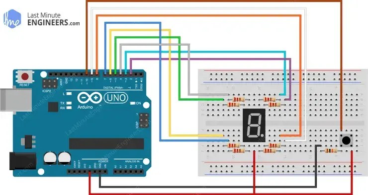
Wiring
We’ll retain the same Arduino setup as in the previous example, but this time, we’ll incorporate a tactile switch for rolling.
Arduino Code
#include "SevSeg.h"SevSeg sevseg; const int buttonPin = 10; // the number of the pushbutton pin// variables will change:int buttonState = 0; // variable for reading the pushbutton statusvoid setup(){ byte numDigits = 1; byte digitPins[] = {}; byte segmentPins[] = {3, 2, 8, 7, 6, 4, 5, 9}; bool resistorsOnSegments = true; sevseg.begin(COMMON_ANODE, numDigits, digitPins, segmentPins, resistorsOnSegments); sevseg.setBrightness(90);// initialize the pushbutton pin as an input:pinMode(buttonPin, INPUT);}void loop(){// read the state of the pushbutton value:buttonState = digitalRead(buttonPin); if (buttonState == HIGH) {sevseg.setNumber(random(1,7));sevseg.refreshDisplay(); }}Code Explanation:
This sketch bears resemblance to the previous one, with a few distinctions.
We begin by defining the Arduino pin to which the pushbutton is connected. Additionally, we introduce a new variable, buttonState, to monitor the pushbutton’s status.
// the number of the pushbutton pinconst int buttonPin = 10; // variable for reading the pushbutton statusint buttonState = 0;
In the Setup section, we configure the buttonPin as an input.
// initialize the pushbutton pin as an input:pinMode(buttonPin, INPUT);
Within the Loop, whenever a button press is detected, we generate a random number using the built-in function random(min, max). This function accepts two parameters: the lower bound (inclusive) and the upper bound (exclusive) for the generated random number.
void loop() { // read the state of the pushbutton value: buttonState = digitalRead(buttonPin); if (buttonState == HIGH) { sevseg.setNumber(random(1,7)); sevseg.refreshDisplay(); }}Related article
- Step-by-Step Guide: Arduino Integration with I2C LCD Screen
- Arduino LCD Tutorial: How to Interface a 16×2 Character LCD Module
- Arduino RFID Tutorial: Interface RC522 RFID Module and How It Works
- Arduino HC-05 Bluetooth Module Tutorial: Step-by-Step Guide
